Inside CAMT’s NOx Sensor Assembly Line:
Precision, Automation, and Innovation
Behind the Scenes: CAMT’s NOx Sensor Manufacturing Process
At CAMT Automotive, we are committed to producing high-precision NOx sensors that meet the demands of modern emissions control standards. Our fully automated manufacturing process ensures that each sensor is built with uncompromising accuracy, structural integrity, and long-term durability.
This page provides an exclusive look inside our state-of-the-art assembly line, where advanced robotic systems, automated testing, and rigorous quality control come together to create industry-leading NOx sensors. From core component assembly to functional verification and final packaging, each stage of production is optimized to ensure reliable performance, regulatory compliance, and exceptional quality.
Explore our step-by-step process, view detailed production insights, and witness how CAMT is setting the standard for NOx sensor manufacturing worldwide.
Step 4:
Soldering
the
Circuit Board
Step 5:
Visual Inspection of Solder Joints and Circuit Board Glue Filling
Step 6:
Installing the Back Cover
Step 3:
Assembling Circuit Boards and Aluminum Shells
Step 2:
Application of Sealant to the Aluminum Cover and Plug
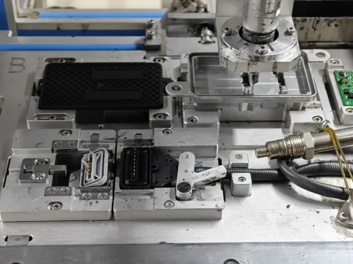
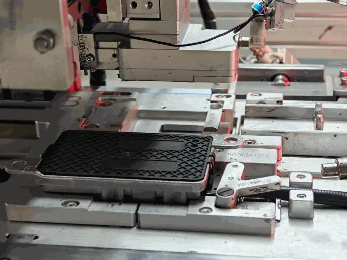
Step 1:
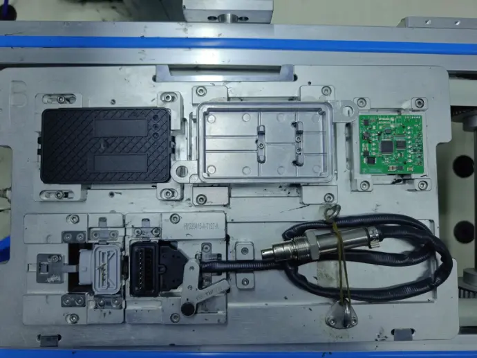
Manual Loading – Rear Cover, Aluminum Cover, Circuit Board, Plug
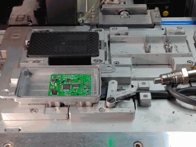
Step 1. Manual Loading – Rear Cover, Aluminum Cover, Circuit Board, Plug, and Wiring Harness
The assembly process begins with careful manual loading of core components, setting the foundation for precise sensor construction. Operators ensure that each component is correctly positioned and secured before moving into automated processing stages.
Key Processes:
Rear Cover and Aluminum Housing Placement
The rear cover and aluminum housing are manually positioned with extreme precision to ensure proper alignment within the assembly jigs. These components form the primary structural shell of the NOx sensor, protecting the internal circuitry and sensing elements from high-temperature exhaust gases, moisture, and mechanical vibrations.
- The housing must fit seamlessly within the designated fixture to avoid misalignment, which could cause sealing failures or unstable sensor performance.
- Operators use calibrated positioning tools and alignment guides to ensure that the housing is placed correctly within tolerance limits, preventing any deviations in later assembly stages.
- Any misalignment at this stage could lead to structural weaknesses, affecting sensor longevity and operational accuracy.
By ensuring that the housing and rear cover are correctly positioned, this step provides a secure foundation for all subsequent assembly stages, allowing for seamless integration of internal components.
Circuit Board and Plug Loading
The circuit board is the central processing unit of the NOx sensor, responsible for interpreting gas concentration data and transmitting signals to the vehicle’s ECU. Proper placement of the circuit board, plug, and wiring harness is essential to ensure consistent electrical performance and durability.
- The circuit board is carefully positioned inside the housing, ensuring that all electronic contacts align with their respective terminals.
- The plug and wiring harness are placed in designated slots, allowing for secure electrical connectivity without the risk of dislodging due to engine vibrations or thermal expansion.
- Automated precision mounting tools assist in positioning, but final verification is conducted manually to ensure all connections are correctly seated before fastening begins.
- Misalignment at this stage could result in faulty electrical signals, sensor errors, or data transmission failures, impacting the accuracy of emissions readings.
By maintaining tight tolerances and precise placements, this stage ensures that the sensor’s internal components are correctly integrated, preventing issues during soldering and testing phases.
Visual Alignment Checks
Once the components are manually placed, trained operators conduct a thorough visual inspection to confirm that each part is correctly positioned, securely fitted, and ready for automated processing.
- Checking for Proper Component Seating: Every component must be fully inserted, flush, and securely in place to prevent misalignment or movement during later processing.
- Identifying Misalignment or Defects: If any component is improperly placed, tilted, or loose, operators adjust them immediately, preventing costly rework or defects that could compromise sensor performance.
- Confirming Structural Integrity: The housing, circuit board, and wiring connections are double-checked for mechanical stability, ensuring that once sealed, the sensor can withstand thermal expansion, vibrations, and external forces in real-world automotive applications.
This stage ensures that all critical components are correctly in place before transitioning to automated assembly. By establishing a strong, well-aligned foundation, CAMT minimizes production errors and enhances sensor longevity, guaranteeing that every unit meets strict OEM and industry standards.
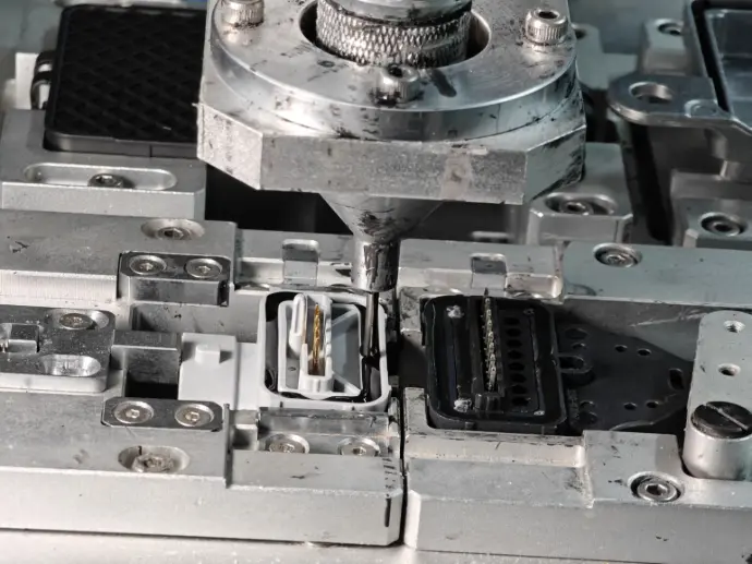
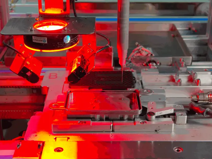
Step 2. Application of Sealant to the
Aluminum Cover and Plug
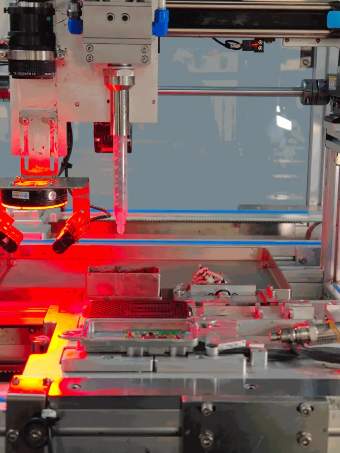
Applying a specialized industrial sealant to the aluminum cover and plug is a crucial step in ensuring the NOx sensor’s long-term durability. This sealant acts as a protective barrier against contaminants such as moisture, dust, and high-temperature exhaust gases, preventing internal corrosion or component failure.
Precision Sealant Dispensing – Achieving Uniform Coverage
The sealant application process is fully automated, utilizing high-precision dispensing systems to ensure even and consistent distribution of the sealant material.
- Automated Nozzle Control: Specialized robotic dispensers carefully control the flow and amount of sealant, ensuring that each unit receives the exact required amount without excess material that could interfere with sensor assembly.
- Targeted Application Zones: The sealant is applied directly to key areas, such as the sensor’s aluminum cover and plug, where protection is most needed. This prevents gaps, leaks, or weak points that could expose the internal components to contaminants.
- Consistent Thickness and Adhesion: The automated system ensures that the sealant maintains uniform thickness, preventing inconsistencies that could lead to air pockets or structural weaknesses in the protective layer.
By using advanced automation, CAMT eliminates human error and variability, ensuring every sensor meets strict quality and durability standards.
Controlled Drying and Adhesion – Maximizing Bonding Strength
Once the sealant is applied, it undergoes a controlled drying and curing process to ensure that it fully bonds with the aluminum housing and plug. This step is essential for creating an airtight, durable seal capable of withstanding high temperatures, vibrations, and prolonged exposure to exhaust gases.
- Optimized Drying Conditions: The curing process is conducted in a temperature-controlled environment, allowing the sealant to harden gradually without premature drying, which could cause cracking or peeling.
- Heat and Chemical Resistance: The cured sealant forms a high-temperature-resistant layer that remains stable even under continuous exposure to extreme exhaust conditions.
- Structural Reinforcement: The fully cured sealant enhances the rigidity of the sensor assembly, ensuring that mechanical stress, road vibrations, and thermal expansion do not cause material separation over time.
By carefully regulating the drying and adhesion process, CAMT ensures that each sensor maintains long-term sealing integrity, reducing the risk of sensor failure due to environmental exposure.
Quality Inspection of Sealant Application – Verifying Structural Integrity
After the sealant has been applied and cured, each unit undergoes a rigorous quality inspection to verify that the protective layer meets industry standards.
- High-Resolution Visual Inspection: Advanced imaging systems scan the sensor to detect any inconsistencies, bubbles, or missed areas in the sealant application.
- Automated Thickness Measurement: Sensors equipped with laser scanning technology measure sealant thickness, ensuring that it falls within precise tolerances for maximum protection.
- Adhesion Testing: Select units undergo adhesion verification tests, where applied force and environmental simulations confirm that the sealant remains intact under stress.
Any unit that does not meet the strict predefined sealant application standards is automatically flagged for rework or rejection, preventing defective units from continuing through the production process.
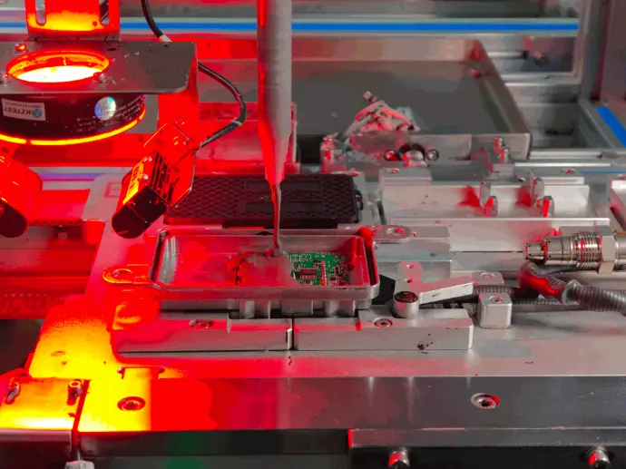
Step 3. Assembly of Circuit Boards
and Aluminum Shells
The circuit board is one of the most vital components of the NOx sensor, responsible for processing sensor readings and transmitting real-time data to the vehicle’s ECU. The aluminum shell provides critical protection against mechanical damage, thermal stress, and external contamination.
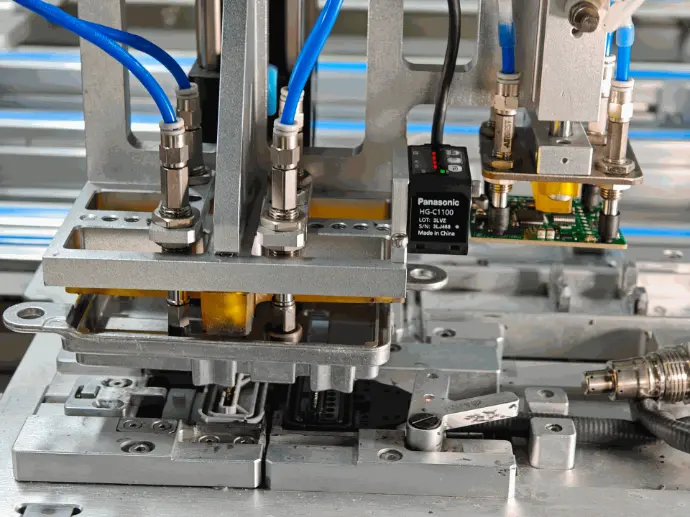
Aluminum Shell Integration – Shielding Electronics from External Stress
Once the circuit board is securely positioned, it is enclosed in a high-strength aluminum shell that provides mechanical reinforcement and protection from environmental hazards.
- Encasing for Maximum Protection: The aluminum shell is designed to fully enclose the circuit board, ensuring that no external contaminants, moisture, or debris can compromise the sensor’s internal components.
- Heat Dissipation and Thermal Management: The aluminum housing is designed to efficiently dissipate heat, preventing overheating of sensitive electronics during prolonged operation. This is especially important for NOx sensors, which operate near high-temperature exhaust components.
- Shielding from Electromagnetic Interference (EMI): The aluminum shell acts as a protective barrier against electromagnetic interference, ensuring that the circuit board’s signals remain strong and accurate without external disruption.
This integration step ensures that the sensor remains structurally sound and fully functional, even when exposed to harsh operating conditions such as extreme heat, humidity, and constant vibrations.
Circuit Board Placement and Securing – Ensuring Stability and Precision
The circuit board must be carefully positioned and secured within the sensor’s housing to prevent electrical interference, misalignment, or damage that could compromise performance.
- Precision Mounting for Stability: The circuit board is aligned and mounted using automated positioning systems that ensure it is perfectly placed within the aluminum housing. Even the slightest misalignment could cause connectivity issues or impact the sensor’s ability to transmit data accurately.
- Secure Fastening to Prevent Vibrations and Shifting: Since NOx sensors are exposed to constant vibrations, temperature fluctuations, and engine movements, the circuit board is mounted using reinforced fasteners and stabilizing brackets that prevent movement inside the housing.
- Electrostatic Discharge (ESD) Protection: Given the sensitivity of the microelectronics, strict ESD control measures are followed to prevent damage to delicate components during handling and installation.
This step ensures that the circuit board remains firmly in place, allowing the NOx sensor to function flawlessly under real-world automotive conditions.
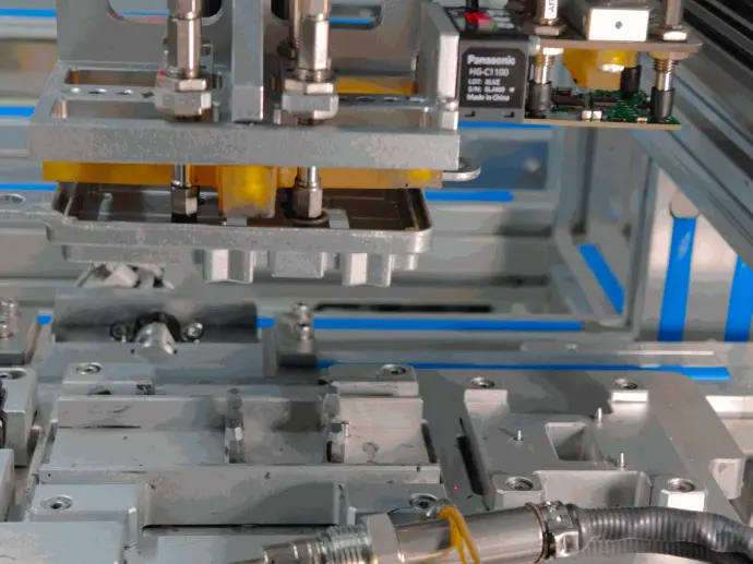
Fastening and Reinforcement – Securing the Sensor’s Structural Integrity
After the aluminum shell is installed, the final fastening and reinforcement stage takes place to ensure that the housing is securely sealed and vibration-resistant.
- Precision Torque-Controlled Fastening: Using high-precision assembly machines, the aluminum shell is tightly fastened to prevent loosening over time due to mechanical stress and vibrations.
- Reinforcement Against External Impact: Additional fasteners and reinforcement features are applied to protect against sudden mechanical shocks, temperature expansion, and pressure fluctuations.
- Sealing for Long-Term Durability: To further ensure the sensor remains airtight and protected, this step includes final adjustments to guarantee an optimal fit between the circuit board, aluminum shell, and fasteners.
By the end of this process, the NOx sensor is structurally complete, with its internal electronics fully secured and shielded, making it ready for final quality control testing and functional verification.
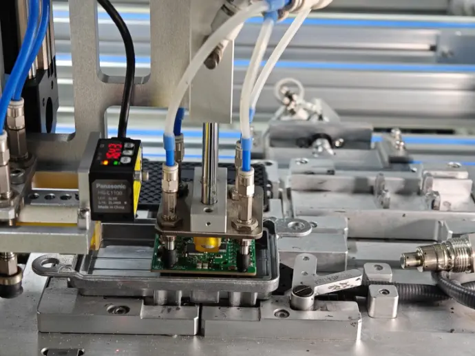
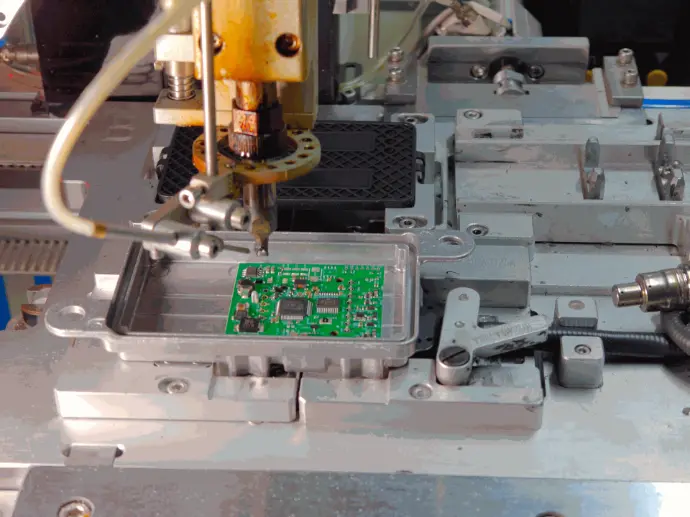
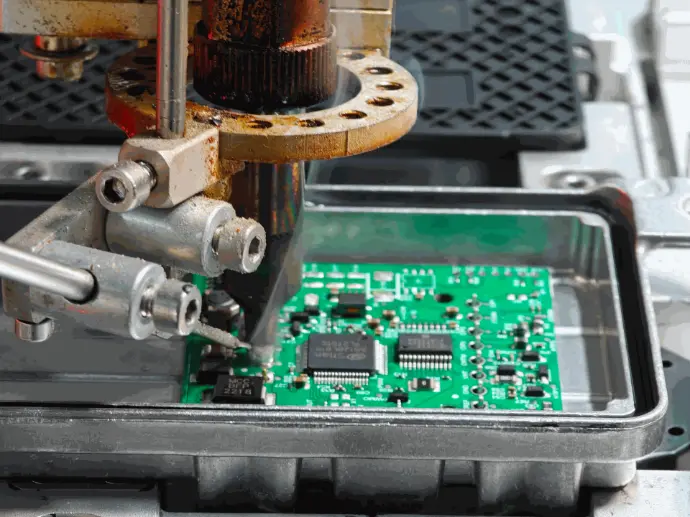
Step 4. Soldering the Circuit Board – Ensuring Electrical Integrity and Long-Term Performance
A high-precision automated soldering process ensures that all electrical connections between circuit board components are securely bonded. This step is critical for ensuring that the sensor can accurately process NOx concentration readings without signal loss or electrical interference.
Precision Soldering for Secure Electrical Contacts
Soldering plays a vital role in creating strong, conductive connections between the sensor’s microchips, resistors, and communication pathways on the circuit board.
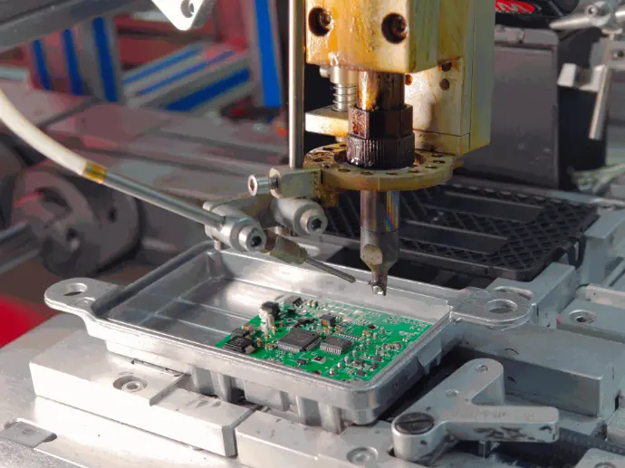
- Controlled Heat Application: Using automated temperature-controlled soldering stations, heat is applied precisely to ensure a strong, even bond between circuit components without causing thermal stress or damage.
- Automated Solder Dispensing: A precisely measured amount of solder is applied to each connection point, ensuring consistent adhesion and conductivity while preventing excessive buildup or weak connections.
- High-Strength Joint Formation: The soldering process creates a durable and corrosion-resistant bond, allowing the NOx sensor to maintain long-term electrical stability, even under constant exposure to engine vibrations and extreme temperature fluctuations.
A properly soldered circuit board ensures that every electrical connection remains intact throughout the sensor’s lifespan, preventing signal disruption or intermittent data loss.
Automated Quality Control and Defect Detection
After the soldering process, every circuit board undergoes rigorous quality inspection to verify that all solder joints are formed correctly and meet industry performance standards. This stage is critical to detect and correct any potential defects before the sensor moves on to the next phase of production.
- Infrared Thermal Scanning for Defect Detection: Advanced infrared imaging technology scans each soldered joint to identify cold solder joints, incomplete connections, or excess solder buildup, allowing immediate corrections.
- Automated Optical Inspection (AOI): High-resolution cameras analyze the soldered components, ensuring that each joint meets the correct size, shape, and adhesion strength requirements.
- Electrical Continuity Testing: Each soldered connection is tested to confirm that electrical current flows smoothly across all circuit pathways, eliminating the risk of signal interference, resistance buildup, or short circuits.
Any defective circuit boards are flagged for rework or removed from the production line, ensuring that only flawless, fully functional sensors continue through the assembly process.
Optimized Conductivity and Signal Stability
The effectiveness of the NOx sensor relies on its ability to process and transmit emissions data with real-time accuracy. Poor soldering can lead to intermittent signal loss, electrical noise, or complete sensor failure, making this step crucial for maintaining stable and precise emissions monitoring.
- Enhanced Conductivity for Accurate Data Transmission: Properly soldered connections ensure that sensor readings are transmitted without resistance loss, allowing seamless communication with the vehicle’s ECU.
- Vibration and Temperature Resistance: Since the sensor operates in high-temperature environments near the exhaust system, soldered joints must withstand thermal expansion and contraction, as well as mechanical vibrations from the engine.
- Long-Term Electrical Stability: A well-executed soldering process prevents oxidation, micro-fractures, or weak joints, ensuring that the sensor maintains high-performance accuracy over years of continuous operation.
By ensuring strong electrical connections, CAMT’s soldering process enhances sensor reliability, signal clarity, and overall durability, making it a critical component of the NOx sensor’s functionality.
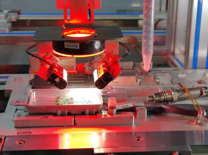
Step 5. Visual Inspection of Solder Joints and Circuit Board Glue Filling – Ensuring Electrical Integrity and Long-Term Durability
Before a NOx sensor circuit board can move to the final assembly phase, it must pass a multi-stage quality inspection process that verifies the integrity of solder joints, electrical connections, and structural reinforcement measures. This step is crucial for preventing manufacturing defects that could lead to sensor malfunctions, inaccurate emissions readings, or premature failure in real-world conditions.
Automated Optical Inspection (AOI) – High-Speed Defect Detection with Precision Imaging
To maintain consistent quality and efficiency, CAMT employs high-resolution Automated Optical Inspection (AOI) systems that scan every assembled circuit board for potential defects in soldering, alignment, and component placement.
- Advanced Camera-Based Inspection: High-speed cameras capture detailed images of the soldered connections, allowing the system to detect cold solder joints, excess solder, bridging (unwanted connections), and insufficient adhesion.
- Pattern Recognition and AI-Based Defect Identification: The AOI system compares real-time images against a preloaded database of acceptable and defective solder joint patterns, instantly flagging any deviations for further review.
- Non-Contact Testing for Delicate Components: Unlike manual inspection, AOI provides a non-intrusive, damage-free way to inspect fragile microelectronics, ensuring that all connections remain undisturbed during testing.
By leveraging automation and AI-driven analysis, this process significantly reduces human error, ensuring that only flawless solder joints proceed to the next stage of inspection.
Manual Review by Trained Technicians – Hands-On Quality Verification
While automated systems provide unparalleled speed and accuracy, certain fine details and edge-case anomalies require human expertise for final verification. At this stage, trained technicians conduct a manual review of circuit boards that were flagged by AOI or selected for random batch testing.
- Magnified Inspection for Microscopic Defects: Using high-powered magnification tools, technicians examine solder joints and electrical pathways to identify issues that may not have been detected by the AOI system.
- Tactile and Visual Assessment of Solder Integrity: Inspectors check for physical irregularities, such as uneven surfaces, weak adhesion, or slight misalignments that could compromise electrical stability over time.
- Functional Verification Testing: If necessary, boards may undergo test-current application, ensuring that each circuit maintains the correct conductivity without resistance buildup.
By integrating both automated and manual inspection procedures, CAMT ensures that every circuit board meets the highest standards of precision and durability before proceeding to the next stage of assembly.
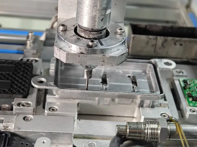
Glue Filling for Added Durability – Reinforcing Circuit Stability
To enhance long-term durability and vibration resistance, a specialized industrial-grade adhesive is applied to critical areas of the circuit board. This step prevents mechanical stress, electrical shorts, and movement-related wear, which can occur when the sensor is exposed to road vibrations, heat cycles, and prolonged operational stress.
- Strategic Application of Protective Adhesive: Glue is applied to high-risk components, particularly around sensitive soldered joints and microchip mounting points, to prevent shock-induced displacement.
- Heat-Resistant, Non-Conductive Formula: The adhesive used in CAMT’s NOx sensors is engineered to withstand extreme temperatures, ensuring that it does not degrade, crack, or interfere with electrical conductivity over time.
- Minimizing Vibration-Induced Failures: Road vibrations and engine movement can cause microfractures in solder joints, leading to intermittent signal loss or complete sensor failure. The glue-filling process creates an additional layer of mechanical reinforcement, preventing such failures.
This reinforcement phase ensures that the sensor’s internal electronics remain structurally sound and functionally reliable, even in harsh driving conditions.
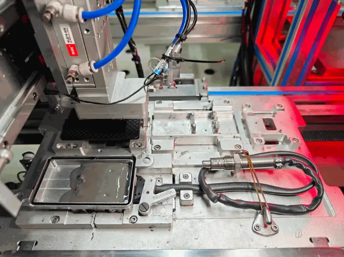
Step 6. Installing the Back Cover – Finalizing the Structural Integrity of the NOx Sensor
The installation of the back cover marks the final stage of structural assembly, ensuring that the NOx sensor’s internal components are fully protected from external elements. This critical step provides reinforcement against environmental exposure, mechanical stress, and high-temperature conditions while also sealing the sensor for long-term durability and operational reliability.
Precision Alignment of the Back Cover – Ensuring a Perfect Fit
The back cover must be precisely aligned and seated onto the sensor assembly to guarantee a secure enclosure that maintains the sensor’s mechanical integrity and environmental resistance.
- High-Accuracy Positioning Tools: Automated alignment systems position the back cover to exact specifications, ensuring a flush, even fit over the sensor housing.
- Component Clearance Verification: The system checks for proper clearance between internal components and the cover to prevent undue pressure on delicate electronic parts, which could cause electrical failures or misalignment.
- Elimination of Gaps or Misalignment: Any misaligned cover placement could result in loose fittings, improper sealing, or potential exposure to external contaminants, which is why strict tolerance checks are performed before fastening.

Automated Fastening and Sealing – Securing the Sensor’s Protective Layer
Once aligned, the back cover is securely fastened using automated torque-controlled screws, ensuring a tight, uniform seal that maintains the sensor’s structural integrity and durability under extreme conditions.
- Precision Torque-Controlled Screwing: Each fastening point is precisely torqued to prevent overtightening, which could cause structural stress, and eliminate under-tightening, which could leave gaps or result in loose fittings.
- Sealing Against Contaminants: The fastening process ensures that the sensor remains airtight and resistant to dust, moisture, and exhaust fumes, which could otherwise degrade performance over time.
- Vibration and Shock Resistance: The fastening system reinforces the sensor’s mechanical stability, ensuring that the cover remains firmly in place even under prolonged exposure to vehicle vibrations, temperature fluctuations, and environmental stress.
By implementing automated fastening technology, CAMT ensures that each sensor maintains consistent quality, durability, and resistance to harsh conditions, ultimately extending its lifespan and performance efficiency.
Final Quality Check Before Functional Testing – Verifying Structural Integrity
Before the assembled sensor proceeds to the functional testing phase, it undergoes a comprehensive final quality inspection to ensure that the back cover is properly installed and secured. This step is critical to prevent sensor defects, misalignment, or contamination risks before performance validation.
- Visual and Automated Inspection: High-resolution imaging systems and trained quality control personnel examine the sensor for any loose fittings, misalignment, or gaps that could compromise its durability.
- Structural Integrity Validation: The enclosure is tested for resistance to external forces, ensuring it can withstand pressure, heat expansion, and physical stress without compromising the internal electronics.
- Sealing Confirmation: The final sealing check ensures that no entry points for dust, water, or exhaust contaminants remain, preventing premature failure in real-world operating conditions.
Once the sensor passes all structural and quality assessments, it moves on to the functional testing phase, where its operational accuracy, emissions detection capability, and electrical performance are rigorously validated.
Help Us Drive Innovation in Manufacturing
Join us in shaping the future of precision engineering and cutting-edge production technology.